How to Use Laser Scanning to Customize Your Van Build
- Bill Allen

- Jan 24, 2023
- 7 min read
Read on to learn how to extract polyline contours from a LiDAR point cloud. In this case, for fitting and fabricating your custom van conversion.
Many custom van conversion shops and DIYers can attest to the need for a proper template cut-out. From rigid foam insulation to finished wall panels, rectilinear materials need to conform to unique contours in each van year and model.
Cutting and crafting materials for fit and finish is a task on its own, but getting the correct measurements? Another challenge entirely. This is where laser scanning comes in.

The Reason:
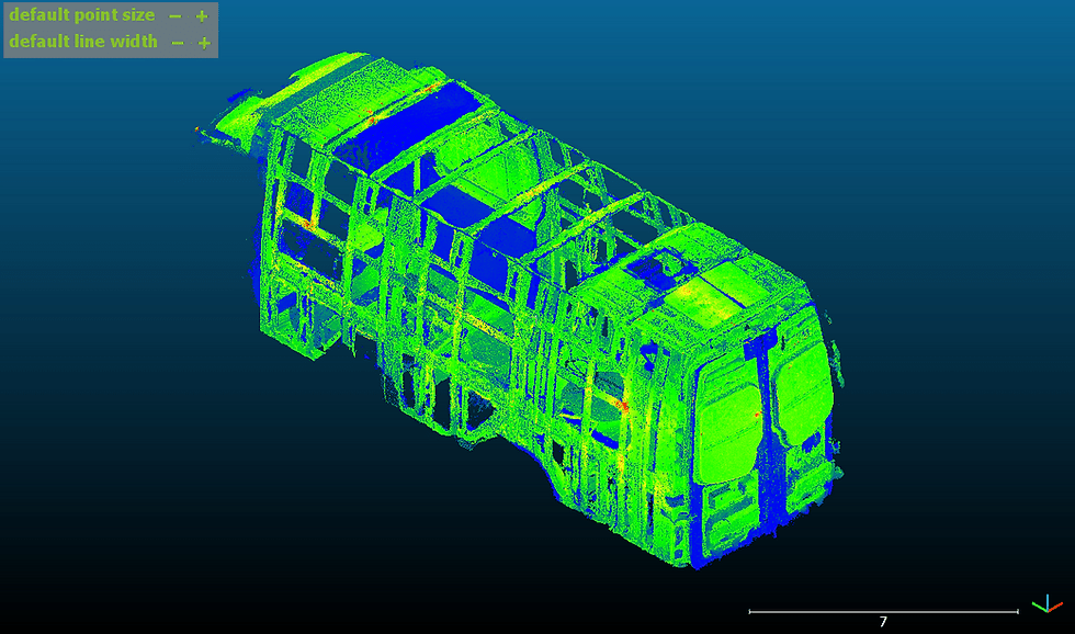
A dense LiDAR point cloud of the van body interior allows the builder to leverage a significantly more efficient, more accurate workflow. With a point cloud, you can take curved dimensions, measure exact angles, and test fit your CAD models. With any dimension available at your fingertips, you will also reduce the numerous trips between your van and shop for measurements.
The possibilities expand once you begin processing points to extract CAD geometry: polylines, surfaces, and meshes can be mathematically fit to selected points and exported for use in other CAD software. This allows you to begin automating your process and scaling your output.
We take advantage of laser scanning a van conversion in our most recent YouTube video, “How to Use Laser Scanning to Customize Your Van Build” found at the bottom of this page. In the quick demo, you will see the process used to:
Manually clean point cloud noise
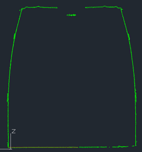
Create contour profile slices every 6" along the van
Export contour polylines to DXF format
Why DXF (Drawing Exchange Format)? Because it is super versatile and will import into most CAD and CAM software. In this case, the DXFs are to be traced in SolidWorks to create native model geometry.
The Tools:
Laser Scanner: Leica BLK360, FIELD 360 iPad app
Scan Registration: Leica REGISTER 360
Point Cloud Cleaning: Leica REGISTER 360, Autodesk ReCap
Point Cloud Processing: CloudCompare
CAD software: Autodesk AutoCAD
Workstation: BIMBOX Stryker M15
The Process:
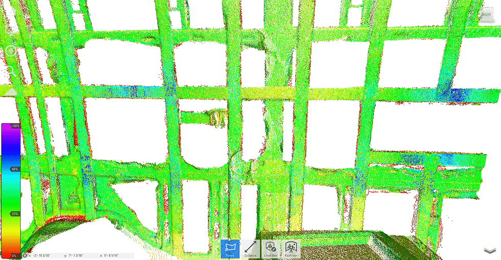
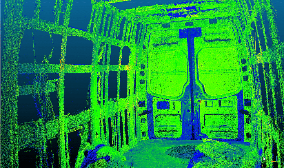
The Leica BLK360 proved to be the perfect terrestrial scanner for the job: lightweight and compact is exactly what you need for the small space, which is no more than 20 feet long and less then 7 feet wide. I captured five to six setups per van, adjusting the tripod to various heights to minimize “shadowing” in the point cloud.
Because I was creating links on the iPad as I scanned, registering the scans in REGISTER 360 was a breeze. In most cases, I added a few additional links between setups to tighten the loop and bring my error down to 2mm or less. For reference, 1/16th of an inch is about 1.6mm.
Once the registration was tightened up, I quickly deleted any points outside the van’s interior and exported to .RCP, Autodesk ReCap’s point cloud project filetype. Why ReCap? I wanted to manually remove points I knew to be bad. I would try algorithmic filtering later on, but there were point subsets I wanted 100% gone.
ReCap is pretty great as a point cloud viewer (given your computer can handle it). I do not often choose it for editing, but using the Lasso tool to delete points is quick and intuitive. While REGISTER 360 has the same tools for manual cleaning, they don’t feel as nimble as ReCap’s mouse navigation and section boxes.


Once I felt the majority of bad points were deleted, I exported the project to .PTS format to import into CloudCompare. If you work with point clouds and have not used this software, check it out. It is free and open source, which is incredible given some of its advanced tools.
The tools I was most interested in: Cross Section and Export Multiple Slices. With these I could semi-automate the extraction of contour lines along a given direction. Before I produced the slices, however, I wanted to try cleaning my point cloud a bit more with algorithms.
I experimented with CloudCompare’s statistical outlier removal (SOR) for a bit but couldn’t strike a great balance between removing noise and keeping good albeit sporadic points. This was one of the reasons I mostly stuck with a manual cleaning process. I did end up using a minimal SOR that cleaned maybe a couple hundred points—not necessarily significant but this slightly increased the cloud quality by removing far outliers without sacrificing much fidelity.

In the GIF, you can see the difference between the manually cleaned cloud, a minimal SOR filter and a more aggressive one. Note that reducing a point clouds density will be beneficial for performance so it's usually worth testing on most projects. Read more about the impact and lessons of point density in the Results section below.
As stated earlier, the real reason I’m using CloudCompare is to slice, dice, and export my point cloud into DXF contour outlines. Even if the contours need cleaning, tracing a DXF instead of a point cloud will put much less stress on my machine.
The process turned out simpler than originally thought. Basically, you select the cloud you want to slice, set the direction to slice along, and determine the slice size and intervals. Not only will it chop up the point cloud, it will also extract polylines fit to each individual slice—with one click! Incredible!

You decide the level of detail for fitting the polylines. Too coarse and the line isn’t accurate enough, too fine and the line with have hundreds of tiny segments. I spent a lot of time on this step trying to find a happy medium. Ultimately, I decided it might be less effort to simplify or trace specific contour slices in AutoCAD as long as I have accurate contours.
The entire process took some trial and error. The end goal was to deliver DXF contours that can be sent to a CNC mill and there are still a few kinks to work out. Overall, this process is an effective and more accurate way to extract unique geometry from a point cloud. Though, it does require someone with a little skill in LiDAR capture and processing methods as well as CAD knowledge.
Looking back, I would have taken even more setups with the BLK and ditched the tripod for a few of them. One of the advantages of the BLK360 is it can scan without being attached to a tripod (above-ceiling-tile scanning, anyone?). A few more setups from both floor and ceiling height would have further minimized shadows and, dare I say, allowed “total coverage” to be a very attainable goal.
I would also add setups to capture open doors and the van’s undercarriage. This would be extremely helpful to have when creating door panel templates and installing undercarriage equipment (i.e. water tanks).
The amount of scan coverage was important, especially when it comes to tracing polylines. It would have been better to overshoot the number of scans needed and filter out unneeded points afterwards.
This would have made using CloudCompare’s SOR filter more viable. By having greater point density, the SOR tool will have a better idea of which points are good and which are outliers. If making meshes from point clouds are your thing, you will want to start higher point densities and cleaner clouds. You can always reduce the number of points later and simplify surfaces.
Though, this is where the scanner ran into some challenges. Scanning reflective or glossy surfaces is always tricky; in order for the scanner to create a point, laser light energy must bounce off a surface and travel back to the scanner head. In the case of reflective surfaces, the laser bounces all right, but usually not in a way that travels back to the scanner.

This phenomenon is best explained with a picture (see image). Essentially, you want a rougher aka diffuse surface so the laser can scatter better, which allows more light energy to travel back to the scanner head.
With that in mind, you can imagine what highly reflective automotive paint and smooth, curved surfaces will do to a laser. If the paint color is black, expect even more trouble: black absorbs all wavelengths of light (whereas white reflects all wavelengths), so the laser will lose additional energy.
One solution to this problem is use scanning spray—either a fine mist or chalk-like dust that will coat reflective or transparent surfaces to make them more diffuse. Some sprays evaporate, some you must clean up manually. Either way, the potential cleanup required makes this is a step you want to take before starting any finishes in your van. (Disclaimer: I have not tested this, try at your own risk)
Moving on to DXF extraction from the point cloud. There were a few ways to accomplish this bit and I experimented with a lot of them. In the end, I determined it would be more accurate to trace over the DXF exports that came from the point cloud. This is due to the numerous segments I chose to generate in CloudCompare when fitting a polyline to a point cloud. Sending the raw DXF to the CNC mill would result in ridiculously wonky edges among other things, aka not good.

I tried for a while to simplify the polyline with AutoCAD commands but to no avail. The resulting path was too complex to send to any CAM software. It ended up be easier to trace a spline over the half the outline, then mirror that spline and make any adjustments.
If you have a machine that can handle point clouds, you may consider skipping the DXFs altogether and opt to trace point cloud slices instead. Both AutoCAD and Revit have this functionality so pick your poison. I have yet to do the drafting in Revit, but I have a feeling it will be easier than it was in AutoCAD. But that is a post for another time.
I hope this post helps you optimize your van conversion with a scan-to-CAM-to-fab workflow (that's a thing, right?). Feel free to ask any questions about the process in the message box below or channel comments. Be sure to subscribe to our YouTube channel to get notified when new videos and blog posts go live.
Thanks for reading, check in next week for our latest video and blog post!


